What is Geometric Dimensioning and Tolerancing
Geometric dimensioning and tolerancing provides a uniform method of stating part requirements so that there is a standard for interpretation. It ensures that design requirements are stated as they relate to a part’s function and that part’s relationship to other parts used in an assembly. This, in turn, ensures the interchangeability of parts in a manufacturing environment.
Geometric dimensioning and tolerancing is widely used in European industries, and its use is rapidly growing in the United States. A majority of government contracts use geometric tolerancing; other industries are also finding that its use as a universal engineering drawing language and technique can assist with productivity and quality.
Primary references on the subject of geometric dimensioning and tolerancing include Lowell W. Foster’s GEO-METRICS II (The Application of Geometric Tolerancing Techniques) published by Addison-Wesley, and the American National Standards Institute (ANSI) Dimensioning and Tolerancing,Y14.5M-1982, published by the American Society of Mechanical Engineers. These standards are applied throughout the world with some exceptions relating to International Standards Organization (ISO) standards. These exceptions are noted in the ANSI document Y14.5M-1982.
Geometric Tolerancing
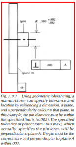
Geometric tolerancing is the concept of categorizing tolerances used to control form, profile, orientation, location, and runout. This clearly defines the engineering intent, or in many cases, provides the true position that may result in a bonus tolerance.
Geometric dimensioning and tolerancing provides for the maximum producibility of a part by allowing maximum production tolerances. It can provide “bonus” tolerances in many applications and will more easily fit a particular manufacturing process capability. In the long run, this saves money by reducing production costs.
Dimensioning and Tolerancing
Foster states that geometric dimensioning and tolerancing is the dimensioning and tolerancing of a drawing with respect to the actual function or relationship of part features. Dimensioning is a means to define the size or geometric characteristic of a part or part feature. Tolerance is the total amount by which a specific dimension can vary and is the difference between the minimum and maximum allowed dimension. Geometric tolerance is the general term applied to the category of tolerancing used to control form, profile, orientation, location, and runout.
Feature and True Feature
The true position of a feature is the theoretical exact location of a feature established by dimensioning. A feature is a physical portion of a part, such as a surface, hole, or slot. The limits of the part’s features must be defined with minimum and maximum tolerances specified for that part’s function.
Material Condition
Maximum material condition (MMC) is an extreme condition of a feature that contains the most material (i.e., minimum hole diameter, maximum shaft diameter). Least material condition is the other extreme condition of a feature that contains the least material (i.e., the maximum hole diameter, the minimum shaft diameter). It is the application of the material condition in relation to other features in geometric tolerancing that will allow for “bonus tolerances” or zero tolerances on a feature. This material condition is the boundary generated by the collective effects of the specified MMC size limit of a feature and any applicable geometric tolerances.
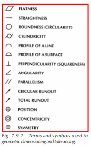
The terminology and corresponding symbols used for geometric dimensioning and tolerancing are listed in Figure 7.9.2.
Along with providing interchangeability of mating parts, and uniformity and convenience in the drawings, geometric tolerancing provides a common language that accurately and reliably reflects the engineering design requirements. This translates into dollars saved and maximum producibility, a must in this new era of high technology and quality improvement.