What is Torque Auditing
Measuring fastener torque on an ongoing basis for quality control purposes is called torque auditing. To help understand the need for torque auditing, review some of the basic principles of torque measurement that follow. Some case studies of torque auditing appear in the Applications section.
How Fasteners Fasten
The purpose of a fastener is to clamp parts together. Engineers select fasteners (nuts and bolts) by how much tension or clamp force is necessary to maintain the integrity of the joint.
In the case of a bolt, the tension derives from applying enough twisting force (torque) to the head to actually stretch the bolt. In the example in Figure 7.8.1, the bolt is threaded into the lower metal piece and torque is applied until the head of the bolt is seated. After the head is seated, additional torque is applied resulting in bolt stretch. This stretch is the source of the tension that will maintain a clamping force holding the two pieces together.
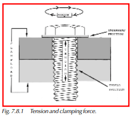
The amount of torque applied should not exceed the amount that will stretch the bolt beyond the “elastic” region (see Figure 7.8.2). Staying within the elastic region means that if we loosen the bolt it will return to its original length. This is the region that engineers target when specifying installation torque values.
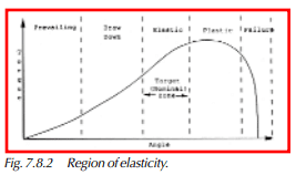
Stretching the bolt beyond the elastic region into the plastic region begins to permanently stretch the bolt. If we then loosen the bolt it will not return to its original length, but will have been permanently stretched, and even though it may not be visible, the bolt has been weakened. This will, of course, weaken the whole assembly due to an unreliable joint.
Applying torque sufficient to stretch the bolt beyond the plastic region into the failure region will cause the bolt to break. One way to measure fastener tension is to measure the length of the fastener after installation and compare it to its length at rest. Since this is usually impractical, torque measurement is used as an indication of tension.
What is Torque?
Torque is the twisting force applied to an object in this discussion a fastener. Rotational force, or torque, can be expressed in several different units of measure, i.e., Foot Pounds, Inch Pounds, or Newton Meters.
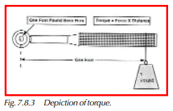
One Foot Pound (Ft. Lb.) is the rotational force, seen at the pivot point, resulting from attaching a One Pound weight at a distance of One Foot from an arm’s pivot point. See Figure 7.8.3.
One Inch Pound (In. Lb.) is the rotational force, seen at the pivot point, resulting from attaching a One Pound weight at a distance of One Inch from an arm’s pivot point.
One Newton Meter(Nm) is a measure of torque in the metric system. A Newton Meter is equivalent to 1 kilogram-meter per second squared.
(1 Newton Meter = .73756 Foot Pound)
Conversion Tables
Torque can be expressed in several types of “units” when expressing a wrench’s capacity. These same units are used to specify a limit set or audit target for a fastener. Converting from one unit of measure to another is done by applying a conversion factor. For example:
If 1 Foot Pound = 1.35582 Newton Meters (from conversion table).
and
you have a torque wrench that is rated for 50 Ft. Lb.
And
you want to determine the wrench’s rating in Newton Meters.
Next
Convert from Ft. Lb. to Nm by multiplying 50 x 1.35582 = 67.79
so
A 50 Ft. Lb. wrench is also a 67.79 Nm wrench.
Conversion Factors
1 Foot Pound = 1.35582 Newton Meters
1 Newton Meter = .737562 Foot Pounds
1 Foot Pound = .138255 Kilogram Meters
1 Kilogram Meter = 7.23301 Foot Pound
(Table 7.8.1. Torque Conversion Factors)
Torque Measurement
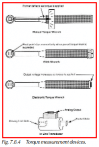
Torque can be measured mechanically or electronically. Some common measurement
devices are shown in Figure 7.8.4, and include:
Manual Torque Wrench
One mechanical measurement method utilizes a handheld wrench, which provides a visual interpretation of the torque seen at the pivot point. The readout can be a simple pointer and scale indicator or a mechanically driven dial indicator. Some varieties indicate the maximum value seen in a measurement cycle. These types of wrenches can be used to measure “peak” torque values.
Click Wrench
Another mechanical method uses a wrench that briefly releases or clicks at an adjustable point in a range of torque values. This type of wrench can only indicate whether a measured torque value is greater or less than a set value.
Electronic Torque Transducers
Torque transducers are devices that convert torque energy into electrical energy. The transducer itself consists of a resistor network (bridge) that is affected by the amount of strain (torque) placed on a mechanical pivot point.
These transducers are built into either handheld wrenches or in-line devices to provide an electrical signal that is proportional to the amount of torque being applied to the pivot point. This output voltage can be interpreted by a variety of devices (i.e., the DataMyte 3053) into a converted digital value representing events occurring at the pivot point.
Transducers are rated for maximum ranges; for instance, a 100 Ft. Lb. wrench would be used in an application where the measured values range between 0-100 Ft. Lbs.
Handheld torque wrenches are typically used to audit previously installed fasteners. In-line transducers are used to monitor a powered installation tool’s torque characteristics during an installation cycle.
Torque and Clamping Force
Since torque is used to put tension in a fastener, the measurement of fastener torque should tell us something about the clamping force of a joint. But torque measurement is by no means a direct indication of clamping force. Other variables are involved.
For one thing, only a small part of the torque applied to a fastener contributes to clamping force. The rest, as much as 90%, is used to overcome friction. Some torque is also absorbed by the fastener shank when it twists slightly.
The major factors that determine clamping force are shown in Figure 7.8.3. The quality of the engineering of a joint includes the physical characteristics and the torque specification. Proper installation includes both assembly and application of fastening torque. If everything is done correctly, the desired clamping force results. Any variation will affect clamping force. Differences will be due to changes over time, such as metal fatigue and the ability of the auditor and torque tool to get an accurate reading.
Torque Auditing Methods
There are two common ways to audit torque:
- Static — using handheld torque tools to check breakaway torque.
- Dynamic — using in-line torque transducers to check peak torque.
There is a good deal of difference between these two methods, and advantages and disadvantages to both. The basic characteristics are listed here, and a detailed description follows.
Static torque auditing has these characteristics:
- It is checked after installation.
- The reading accuracy is operator-dependent.
- The differences between how a fastener is installed and how a torque is checked must be taken into account.
- The time between when a fastener is installed and when torque is checked must be taken into account.
- Fairly uncomplicated gauging is used — a torque wrench or torque driver with dial readout, or an electronic (strain gauge) torque tool connected to a handheld data collector.
- A variety of joints and fastener types can be audited with different range torque tools and adapters.
Dynamic torque auditing using in-line torque transducers has these characteristics:
- It is checked during installation.
- The readings are operator-dependent.
- It is used only with powered torque tools, such as nut runners and air ratchets.
- It must be installed in-line with the production tool.
- Strain-gauge type output requires an electronic readout or handheld data collector.
Static Torque Auditing
Static auditing, also known as Audit Torque Breakaway Torque, or Residual Torque is a measurement of the torque required to start to turn a previously installed fastener.
This method of torque measurement involves manually applying additional tightening force to a fastener until the static friction is overcome and the fastener begins to move.
This point of movement bears a relationship to the amount of torque originally applied to the installed fastener. With this approach, installation methods can be checked without interrupting the assembly process.
This method of auditing can be implemented with manual wrenches that incorporate visual readouts. However, the accuracy of the audit is very operator dependent.
If the wrench being used to check the breakaway point is equipped with an electronic torque transducer, the transducer’s output can be connected to the data collector’s analog port and stored as an audited value. This results in improved accuracy due to a lesser reliance on the operator’s interpretation of the results.
For static auditing, the DataMyte Model 3053, for example, can be configured to analyze the transducer’s signal, using a choice of the following three algorithms, shown graphically in Figure 7.8.6:
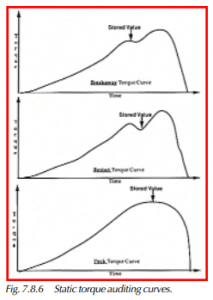
Breakaway
This algorithm samples the transducer’s output looking for the “Breakaway” point. This algorithm automatically detects the momentary drop in force that occurs as the static friction of the fastener is overcome and it begins to rotate. This algorithm would be used when the previously installed fastener’s amount of static friction results primarily from installation.
Restart
This algorithm samples the transducer’s output looking for the “Restart” point. The restart point is a measurement taken at the moment when resistance to rotation first occurs after the “Breakaway” point has been passed. This algorithm is useful when factors such as paint or temperature are adding to the fastener’s normal amount of static friction.
Peak
This algorithm samples the transducer’s output looking for the highest value seen, and requires more operator sensitivity to fastener movement than the previous two. The user applies pressure until fastener movement is observed; then pressure is released. This algorithm is useful when the breakaway or restart points are very gradual in nature due to “softness” of the joint, or if the entire assembly tends to move when audited. Examples include joints that incorporate gaskets, metal to plastic joints, or suspended assemblies.
Sources of Variation between Installation and Breakaway Torque
Below are some of the areas that can make a breakaway reading different from the installation torque specification:
Actual installation versus the specification
The torque achieved at installation may not be the same as the specification. The design of the joint and fastener, its assembly, the performance of the operator, and the accuracy of the torque tool affect the installation. Using adaptors, torquing the nut side or bolt side, and tightening speed all greatly affect actual torque.
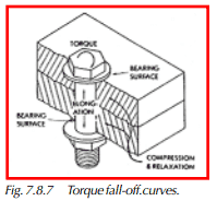
Torque fall-off (joint relaxation)
In as little as one hour after installation, the bearing surfaces of a joint will fatigue due to the compression from clamp load. See Figure 7.8.7. This tends to reduce the torque required to achieve breakaway.
Hard joints and soft joints
Hard joints, such as metal-to-metal with a locking fastener, will have a more pronounced (and detectable) breakaway than joints using a soft gasket or holding softer materials. Breakaway may be imperceptible in some types of joints, such as pipe-threaded junctions, due to the composition of joint materials and the nature of the threads.
Tightening speed (frictional coefficients)
Speed affects a torque reading because the coefficient of friction varies with it. Since the greatest amount of torque is used to overcome the friction in the joint at rest and restart further tightening motion, friction contributes a great deal to variability among readings. Generally, the tightening speed at installation should be matched during an audit. This is a justification for the use of in-line torque transducers to audit torque on power tools.
Other factors—There are other factors that contribute to differences between installation and breakaway torque.
- Temperature
- Absorption of torque by the joint
- Stress and shearing forces
- Training of the auditor in reading breakaway torque
- Accuracy of the audit method
Dynamic Torque Auditing
Dynamic auditing is an approach where the maximum torque generated during the installation process is measured. This approach involves auditing a powered installation tool as opposed to auditing individual fasteners. The tools monitored in this approach are known variously as nutrunners, impact wrenches, stall tools, etc. In many cases, these tools incorporate a built-in transducer. If this is not the case, an in-line (or slip ring) transducer can be attached in line between the socket and the tool.
This method of auditing is implemented by connecting the 3053 data collector’s analog port to the transducer on the installation tool. The data collector then can monitor the amount of torque being applied to a fastener during the installation process and store the maximum (peak) values seen. The “peak” algorithm would normally be used in this configuration. The installation process does not always yield a simple torque curve with a clearly perceived peak. Things that can obscure the actual peak include:
- Resistance as threads are being cut.
- Initial gasket compression.
- Operator-induced factors.
- Tool-induced factors (Pulsed tools).
The Model 3053 allows a high degree of control of a selected algorithm’s sensitivity to help deal with the previously mentioned variables. For example, signal sample time can be varied between 1 and 50 milliseconds. Sampling can be disabled below a user or selected threshold.
When initially setting these parameters, the data collector’s Torque Curve display capability can eliminate the “trial and error” approach previously required. After each cycle of the tool, a display of the transducer’s signal can be viewed (or printed) to help fine-tune related parameters.
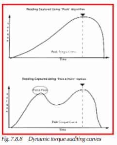
The Torque Curve can optionally be displayed in the data collection mode. This provides a view of the torque/time relationship during each installation cycle. The Torque Curve can also be used to determine which point on the curve(s) the user desires to store as the true peak using the “Pick-a-Point” option.
To use this option, the user simply checks the position of the peak pointer shown on the torque curve and confirms it or moves it to the desired portion of the curve if the algorithm failed to catch the desired peak. This is especially useful in cases where the captured signal reflects uneven pressure seen by the transducer during run down. See Figure 7.8.8.
Dynamic Auditing Example
As previously discussed, it is fastener tension that holds an assembly together. Residual tension on the fastener is the characteristic that is really of concern in a fastener audit. Due to its nature, tension is a very difficult thing to measure. Since fastener tension results from the applied torque energy, it follows that the two bear a relationship to each other. In other words, measuring torque yields a picture of tension.
In this example, we will discuss auditing a bolt used to secure a seat belt anchor point. A 12 mm bolt is used, and the bolt is installed using a powered installation tool that applies 90 Newton Meters of torque. A previous design study found that 90 Nm of torque applied to the fastener in this application yields the desired 8,000-pound clampload on this joint. The powered tool is equipped with a built-in transducer that can read a maximum torque value of 135 Nm, and the tool is adjusted to release when it senses 90 Nm of torque at the socket.
One way to verify that the anchor bolt is actually being installed to 90 Nm (or 8,000 pounds of clampload) is to monitor maximum torque seen at the socket during the installation cycle.
Since this tool incorporates a built-in transducer, it is a simple matter to connect a monitoring device, such as the DataMyte 3053, and electronically capture the “Peak” torque seen during each installation cycle.
The data collector can capture the peak torque values seen during multiple installations. Once collected, this data can then be processed by the 3053 to yield a picture (histogram) of the 6 sigma torque scatter for the tool. The data collector can then compare this 6 sigma distribution to the high and low specification limits the tool is adjusted to work within. This type of study very quickly yields a picture of a tool’s capability (Cpk) to perform the desired task. A Cpk of less than 1.33 is considered insufficient.
Ongoing or periodic checks of this tool using this approach precludes any further auditing of this fastener.
Static Auditing Example
If it is not practical to dynamically monitor a tool on an ongoing basis, a “static” audit can be implemented. As previously discussed, static auditing can be done after a fastener has been installed. Static audits are performed downstream from the installation process. Usually, checks are made on a variety of fasteners as part of an inspection route by QA personnel. A typical 3053 setup is shown in the Appendix.
Using the same fastening example discussed in the dynamic example, the data collector would be set up to interface to a handheld torque wrench instead of an in-line transducer. The significant difference in the gauge setup is the use of the “Breakaway” algorithm instead of “Peak.” The wrench is then used to apply torque (usually clockwise) to the fastener. The operator applies a steadily increasing amount of force until fastener movement is felt, and pressure is then released. The data collector then stores the torque value at which breakaway occurred.
The theory behind static auditing is this:
If 90 Nm of torque was initially applied to reach a specific tightness (or tension), re-applying 90+ Nm of torque will overcome the residual friction and cause the fastener to move. In other words, the audit will find the fastener breaking away at 90 Nm.
The reality of static auditing is this:
To cause a previously tightened fastener to move, the residual friction must be overcome. Since static friction is usually greater than dynamic friction, the breakaway point is usually greater than the installation torque. This fastener’s breakaway point could be in the 90s or in the 100+ Nm range.
Alternatively, if a gasket was part of the assembly, gasket compression could relieve tension through time. This would yield a breakaway value less than 90 Nm due to lessened friction.
Over 200 factors have been identified that can affect the breakaway point in either direction. Prior to creating a static audit setup, acceptable high and low audit limits should be established, since they will probably differ from the specification (installation) limits. The following section discusses some of these factors.